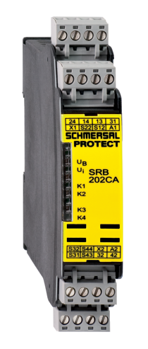
Caracteristici
Ambient temperature, maximum:
45
Ambient temperature, minimum:
-25
Automatic reset function:
Yes
Basic quantity unit:
Piece
Cable section, maximum:
2.5 mm²
Cable section, minimum:
0.25 mm²
Climatic stress:
EN 60068-2-78
Common Cause Failure (CCF), minimum:
65
Conduction resistance, maximum:
40
Contact resistance, maximum:
0.1
Current, Utilisation category AC-15:
6
Current, Utilisation category DC13:
6
Degree of pollution to IEC/EN 60664-1:
2
Diagnostic Coverage (DC) Level, Stop 0:
≥ 99
Drop-out delay in case of emergency, typically:
20
Drop-out delay in case of power failure, typically:
80
EAN ( European Article Number):
4250116201952
EAN (European Article Number):
4250116201952
Earth connection detection:
Yes
eCl@ss number, Version 9.0:
27-37-18-19
Electrical power consumption:
4.4
EMC rating:
EMC-Directive
Enclosure material:
Glass-fibre reinforced thermoplastic, ventilated
Indicated operating states:
Position relay K2; Position relay K1; Internal operating voltage U<sub>i</sub>; Position relay K3
Integral System Diagnostics, status :
Yes
Material of the contacts, electrical:
Ag-Ni, self-cleaning, positive drive
Mechanical life, minimum:
10000000
Mounting:
Snaps onto standard DIN rail to EN 60715
Note (applications):
Safety sensor; Guard system; Pull-wire emergency stop switches; Emergency stop button
Note (Contact resistance):
in new state
Note (General):
Inductive loads (e.g. contactors, relays, etc.) are to be suppressed by means of a suitable circuit.
Note (Short-circuit recognition):
Level 1
Note (Wiring diagram):
The wiring diagram is shown with guard doors closed and in de-energised condition.; Relay outputs: Suitable for 2 channel control, for increase in capacity or number of contacts by means of contactors or relays with positive-guided contacts.; The control recognises cross-short, cable break and earth leakages in the monitoring circuit.; Input level: the example shows a 2-channel control of an Emergency Stop command device (level 1) with external reset button (R), and guard door monitoring (level 2) with feedback circuit (H2).; Automatic start (level 1): The automatic start is programmed by connecting the feedback circuit to the terminals X1/+24 V DC. Automatic start (level 2): The automatic start is programmed by connecting the feedback circuit to the terminals X2/+24 V DC. If the feedback circuit is not required, establish a bridge.; 1 NC contact each time communicates the status of level 1 and level 2
Number of auxiliary contacts:
2
Number of inputs for NC:
3
Number of inputs for NO:
1
Number of safety contacts:
2
ON delay at automatic start:
Adjustable
Overvoltage category:
III
Performance level, stop 0, up to:
e
PFH-Value Stop 0:
0.00000002
Product name:
SRB202CA/QT 24VDC
Product type description:
SRB202CA/QT 24VDC
Protection class of Clips or Terminals:
IP20
Protection class of the Clearance:
IP54
Protection class of the enclosure:
IP40
Pull-in delay at automatic start, maximum, typically:
100
Pull-in delay at RESET, typically:
20
Rated AC voltage for controls at DC minimum:
20.4
Rated control voltage at DC, maximum:
28.8
Rated impulse withstand voltage:
4
Rated operating voltage:
24 VDC -15%/+20%, residual ripple max. 10%
Replacement article number:
101177151
Reset edge detection:
Yes
Resistance to vibrations to EN 60068-2-6:
10 ... 55 Hz, Amplitude 0.35 mm
Restistance to shock:
10 g / 11 ms
Safety Integrity Level (SIL), Stop 0, applicable for:
3
Short-circuit recognition:
Yes
Standards:
IEC 61508; EN 60947-5-1
Storage and transport temperature, maximum:
85
Storage and transport temperature, minimum:
-40
Switching capacity, maximum:
250
Switching capacity, minimum:
10
Terminal Connector:
Screw connection; rigid or flexible
Terminal designations:
IEC/EN 60947-1
Tightening torque of Clips:
0.6
Voltage, Utilisation category AC15:
250
Voltage, Utilisation category DC13:
24
Wire breakage detection :
Yes
Housing
mechanical data